Cow Bayou Drainage Pump Station Complex
Orange, Texas

Overview
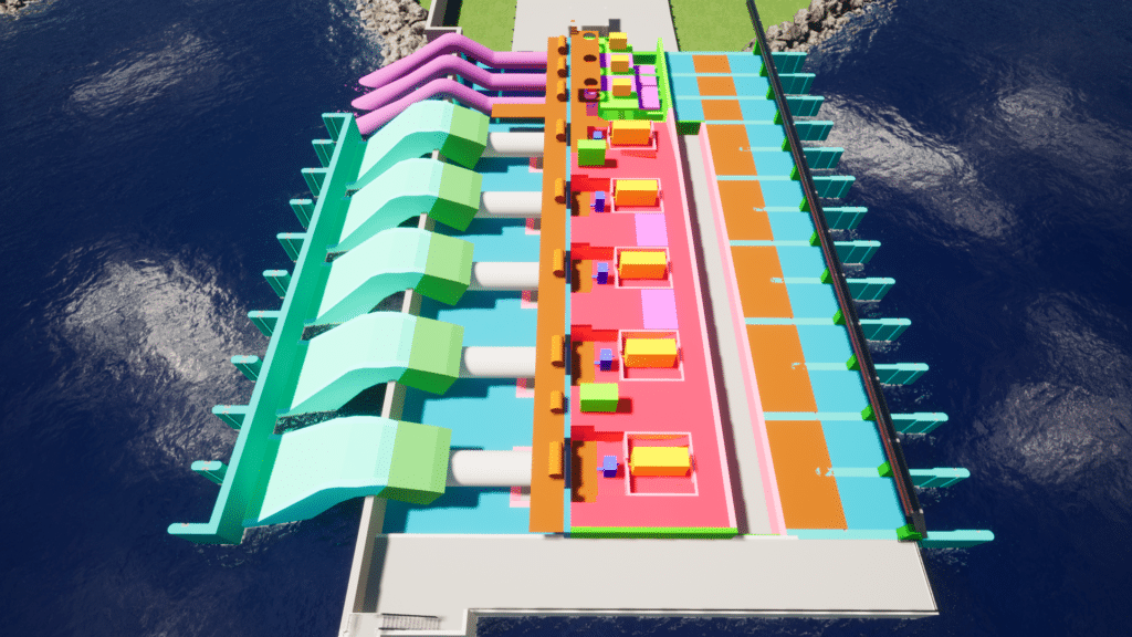
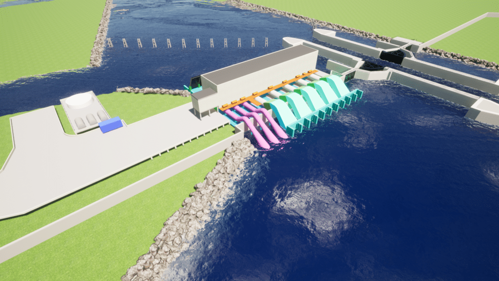
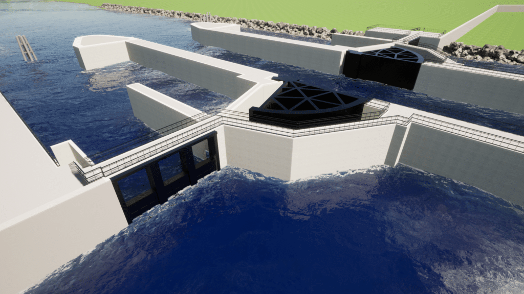
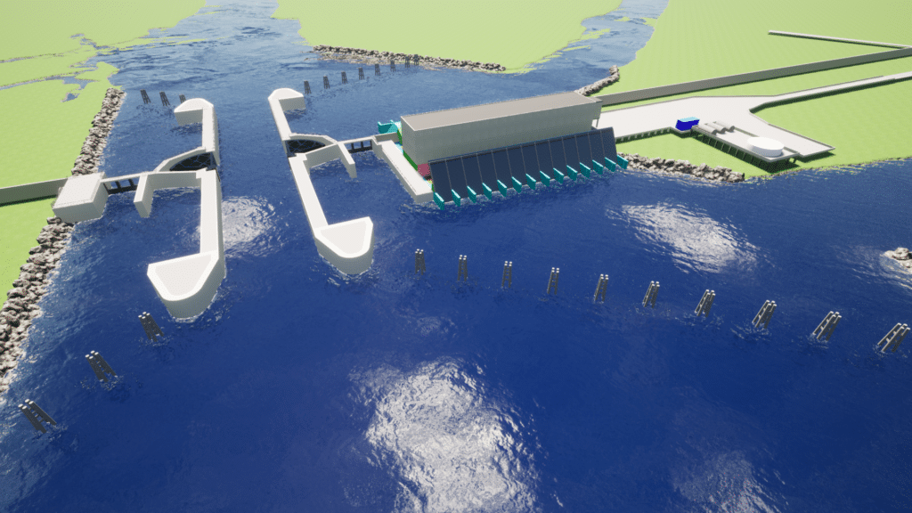
Our team completed 35% design of the 8,190 CFS pump station as part of the Sabine to Galveston Cow Bayou Complex project. The Cow Bayou Complex includes levee tie-ins, floodwalls, sluice gate structures and a sector gate for navigational traffic. The pump station consists of five 1,365 CFS horizontal, vacuum primed pumps requiring 126-inch suction side and 115-inch discharge side with formed concrete intakes; and three 455 CFS vertical self-priming pumps with 84-inch discharge piping.
The preliminary design phase was a joint engineering effort between USACE New Orleans District, Galveston District and our team in which we operate as a one integrated design team. Our design responsibility included structural design, architectural design, civil site work, geotechnical evaluation and design, MII cost estimating, CAD drafting and project management. A unique feature of this project design is that we are an integrated design team with the New Orleans District who is providing the mechanical and electrical design while we are responsible for coordinating the mechanical and electrical design with the civil, structural and geotechnical engineering design. Other project features being designed by our team include dolphin structures which protect the facility above the water level from possible boat impact, a pump station safe house, and a fuel farm and access roads. We designed the project in Microstation 3D, also utilizing Revit BIM 3D modeling for the facilities. Preliminary investigations consisted of extensive geotechnical testing to determine soil suitability, preliminary estimates of dredging based on navigational traffic loads in the Cow Bayou area, and structural calculations to determine the required height of the T-walls, and navigational structures. Preliminary architectural work was also completed to design the safe house that is attached to the main pump station building. The safe house includes all facilities and work spaces for the pump station operators.
The pump station reinforced concrete structure is 250 FT wide by 128 FT long with 8 pump bays and supported by 100 FT long steel H-pile. The vertical pumps, engines, generators, gear boxes, vacuum pumps and electrical equipment are all housed within the pump station building. The structural steel building located above the concrete pump station structure is 43 FT tall and utilizes 8 IN thick precast concrete tilt up wall panels on all four sides of the building. The roof consists of 6 IN concrete slab on metal roof deck attached to the supporting members maintaining a 1:12 slope. All of these features were designed by our engineers and architects.
Our structural engineers, following USACE engineering manuals, designed all permanent project structures associated with the pump station including the horizontal and vertical pump intake and discharge structures, engine and pump support slabs, pump station building, pump station safe house, fuel tank foundation and containment area, water tank foundation, west access bridge, exterior semi-gantry and overhead bridge crane supports, as well as the protective dolphins on the intake and discharge side of the pump station. The pump station and safe house were designed utilizing STAAD software (a 3D structural analysis and design software). Our engineers also reviewed preliminary hydrologic and hydraulic modeling results for the area to set the appropriate protection elevations for all of the risk reduction measures developed as part of this project.
The pump station safe house is a two-story structure 36 FT long by 22 FT wide. The building is supported by cast-in place concrete beams and cast-in place concrete columns. The safe house is a separate structure but abuts to the pump station building. The safe house provides housing for four to six emergency personnel that shall be required to man the facility during a hurricane, and it is designed for tornado force winds. The safe house required a 1,000 gallon per day onsite wastewater treatment facility due to the lack of facilities in the project area. Our civil engineering team provided the wastewater treatment facility design.
The pump station fuel farm consists of an elevated concrete platform structure with containment walls designed to support the three 16K GAL fuel tanks for the pump station. Adjacent to the fuel farm a 55K GAL above ground water storage tank was included as a backup water supply. The sizing was based on providing emergency water for safe house occupants, pump bearing lubrication and safe house sprinkler operations in the event of an emergency.
The geotechnical services included engineering analyses on the soil borings data in which the New Orleans District provided our geotechnical engineers. The team provided recommendations regarding site preparation and drainage, estimates of allowable pile load capacity for support of pump station components and the fuel platform, and estimates of settlement. The geotechnical analysis included performing deep seated stability analyses of the pump station, determining the unbalanced force on the pump station, designing seepage cutoff beneath the pump station, performing analyses to evaluate potential uplift of the pump station during and after construction, determining lateral earth pressures for the wall design, and providing a preliminary design for temporary retaining structures (TRS) to construct the pump station. Analyses were also performed for the design of the dolphins to protect the pump station and gates.
As part of our project management activities and coordination between our design team and the USACE mechanical/electrical design team, we prepared a detailed communication plan which outlined procedures for coordination of design activities and the transfer of information between all parties. The plan addressed scheduling, communication distribution structure, information collection and filing procedures, and a flow chart of personnel and project progression. Our team was responsible for combing the design data for each submittal in which we incorporated the USACE-prepared plans, specs and DDR write-ups into our deliverable set. We also prepared the MII cost estimate for the 35% design package.
Following receipt of the 35% design package, SWD has engaged CERL/ERDC to complete additional hydrologic and hydraulic modeling and changing the acquisition strategy to Design-Build. Currently, our team is awaiting ERDC to complete updated modeling in order to finalize the design package into a Design-Build RFP package which will occur under a future task order


